| Ford Model A |
![]()
![]()

Self-made 2x72" / 50x2000 mm Tilting Belt Grinder - deviations from Jer Schmidt's plans
All chapters on the construction of my 2x72" / 50x2000 mm Tilting Belt Grinder:
Chapter 1: Description and performance features of the tilting belt grinder
Chapter 2: Deviations from Jer Schmidt's plans - Using Sanding belts 2x72" AND 50x2000 mm
Chapter 3: Steel cutting and welding
Chapter 4: Operating panel for motor control
Chapter 5: Spark collector, Spark arrester, Dust collector
Chapter 6: Mobile table with drawers for belt grinder
I deviated from the plan for a few things, partly because I wanted to adapt it to my needs, but also because I procured parts from other sources with different dimensions, which then led to adjustments.
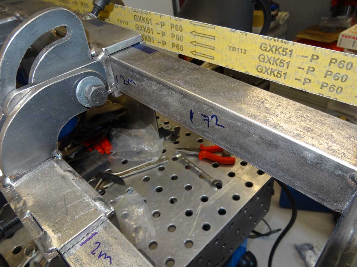
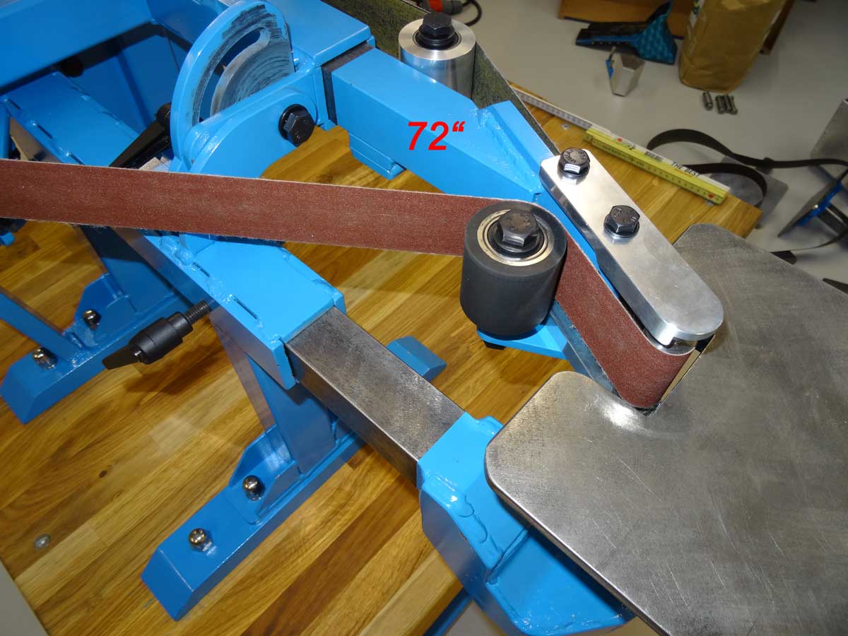
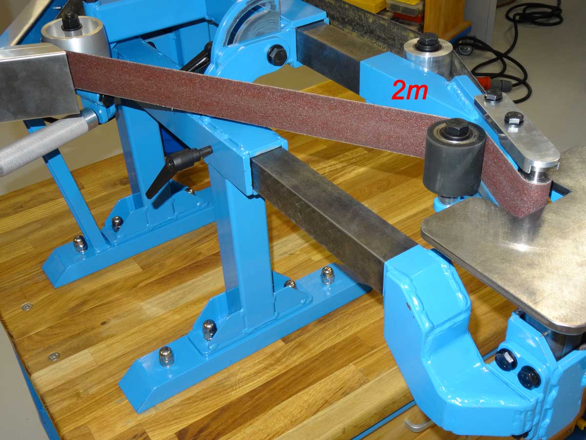
My wish was to build the belt grinder not just for 2x72" OR 50x2000 mm sanding belts and then be fixed to one belt length, but I wanted to remain flexible and use the best sanding belts, regardless of their length. Jer's plans envisaged simply extending the 2 square tubes welded from rectangular profiles by 90 mm each for the 2000 mm version. However, this would mean that I could only use 2000 mm belts in the future and would no longer be able to use the shorter 72" sanding belts. As the whole construction is really very massive, I thought about extending the 40 x 40 mm square profiles instead so that I can pull them out far enough for the 2000 mm belt, but also push them far enough into the tube to work with the 72" belts. I did these tests during welding to see how much I could extend the profiles. My tests then showed that I could extend the profile length of the table holder and the 3 roller holders by 90 mm each in order to work with both belt lengths without restriction and without noticeably weakening the construction. The 40 x 40 mm solid profile can easily withstand such an extension without any negative effects on stability. For the construction, this means that I only need a little more steel and have no extra work. I simply have to cut the 40 x 40 mm square profiles 90 mm further back and with a small change I get a super feature :-)
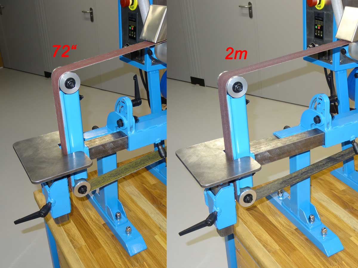
Here you can see the double roller with the short 72" and to the right with the 2000 mm sanding belt version.
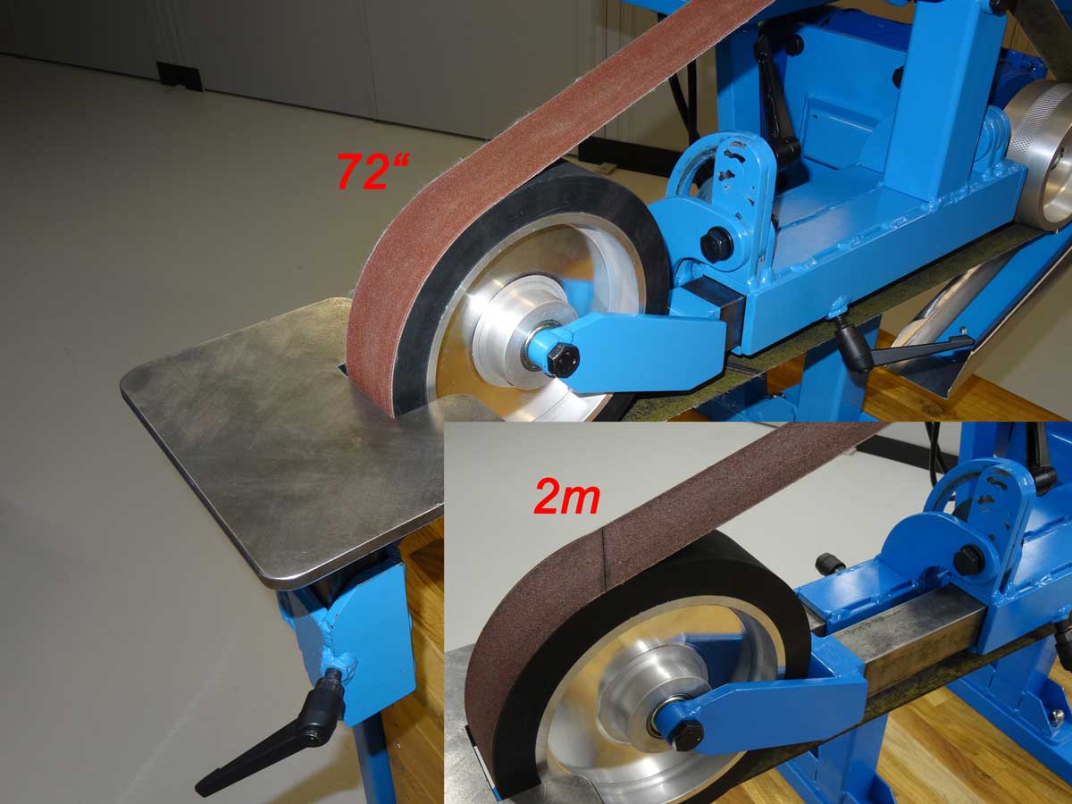
Here is the large rubber wheel with the short 72" and to the right with the 2000 mm sanding belt.
This is the small wheel with the short 72" sanding belt.
And here is the small wheel with the long 2000 mm sanding belt.
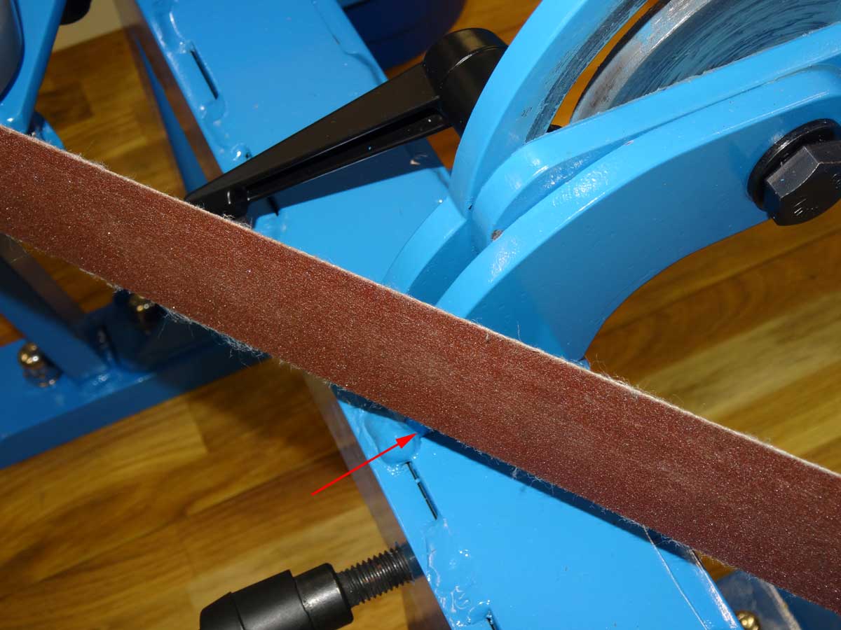
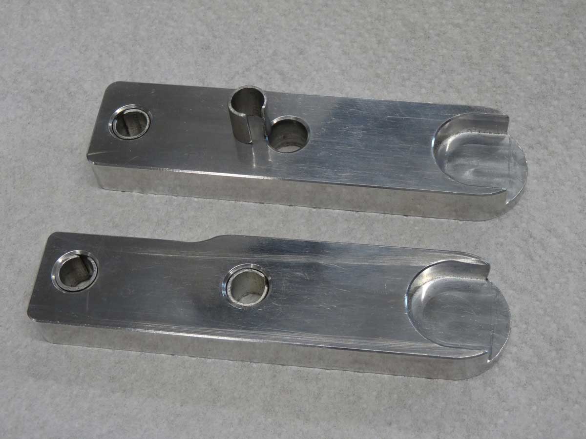
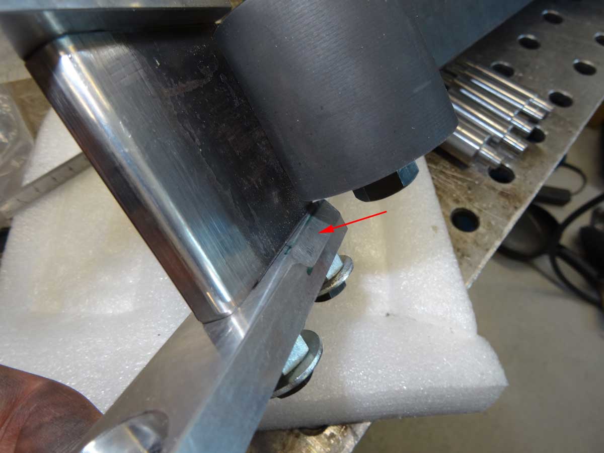
Another issue has arisen as I sourced the wheel holder for the small wheels from a different source than Jer. I noticed that the sanding belt grazed slightly at the marked spot. My aluminum wheel holder has different dimensions and holes than in the plans. I then converted everything to my part and probably made a small mistake and therefore had to remake the holder for the rubber deflector wheel.
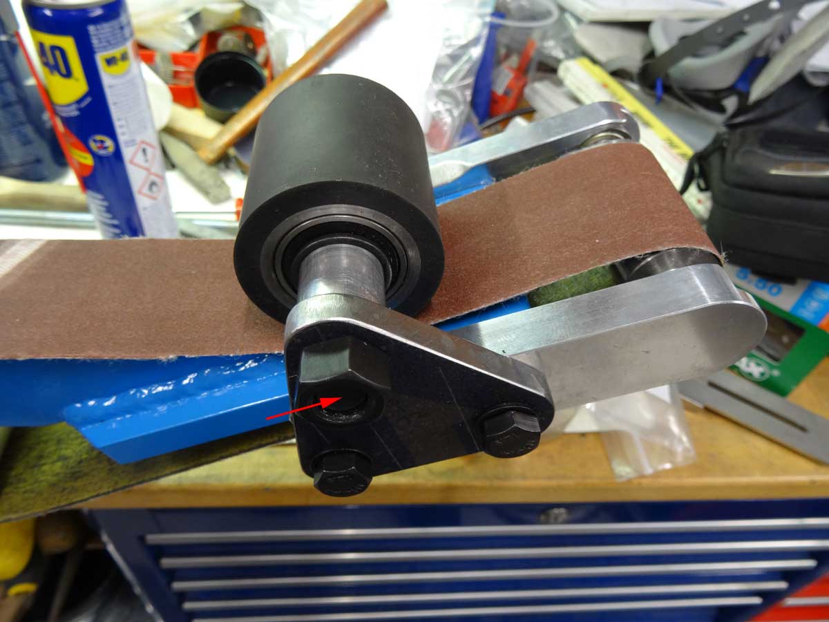
On the new bracket, I moved the hole for the wheel axle 10 mm in the direction of the arrow and it now looks like on the picture. As a result, the strap no longer grazes and there is no functional change.
My 2 wheel holders have a hole that is 2 mm too large and I wanted to compensate for this, so that it is easier to align the 2 arms later. To do this, I cut a strip from 1 mm sheet aluminum. I then took a round steel bar with the right diameter and bent the sheet around this part. This is best done in a vice by slowly turning the part and squeezing it in the vice again and again until a round sleeve is formed. Now I can press these sleeves into the hole.
Another point concerned the shoulder on the side where the sanding belt is threaded. I used the file to create a large phase for this.
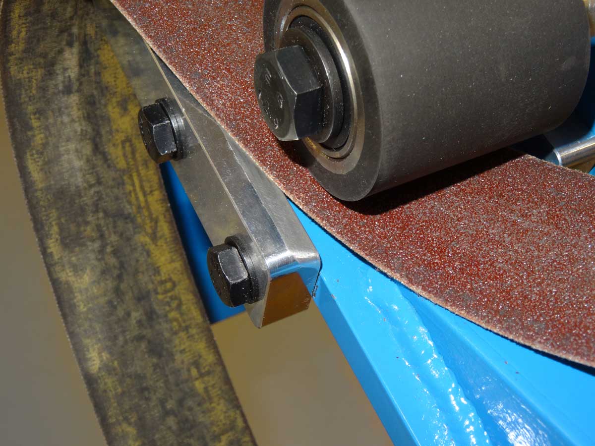
Now I can easily slide the sanding belt under the wheel.
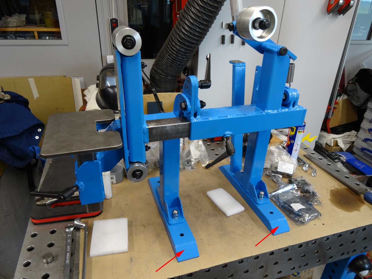
I have fitted even wider feet for my self-made belt grinder. These consist of a 60 x 30 mm U-profile. I did this to give the belt grinder a better stand and I still had to attach the arm for my control panel somewhere. The reason why I didn't weld these wide feet directly in place of the narrow ones is that the large ones would have got in the way when welding and so after the first assembly I was able to test how long the feet had to be so that there was no more tendency to tilt to the left/right, both in the vertical and horizontal position of the sanding belt. With these feet, it stands very well and stable even without being bolted to the table. The only situation where the belt grinder becomes very light at the front is when the table and roller are removed together, as the motor then pulls down on the back.

The cut-out in the steel profile is 1 mm on both sides of the screw. This means that the angle between the vertical and horizontal position is slightly more than 90 degrees. To get back to exactly 90 degrees, I cut a piece from a suitable aluminum tube with a wall thickness of 1 mm and inserted it. It works wonderfully and the advantage is that the stop is more damped and less hard than when the steel screw hits the steel profile directly.
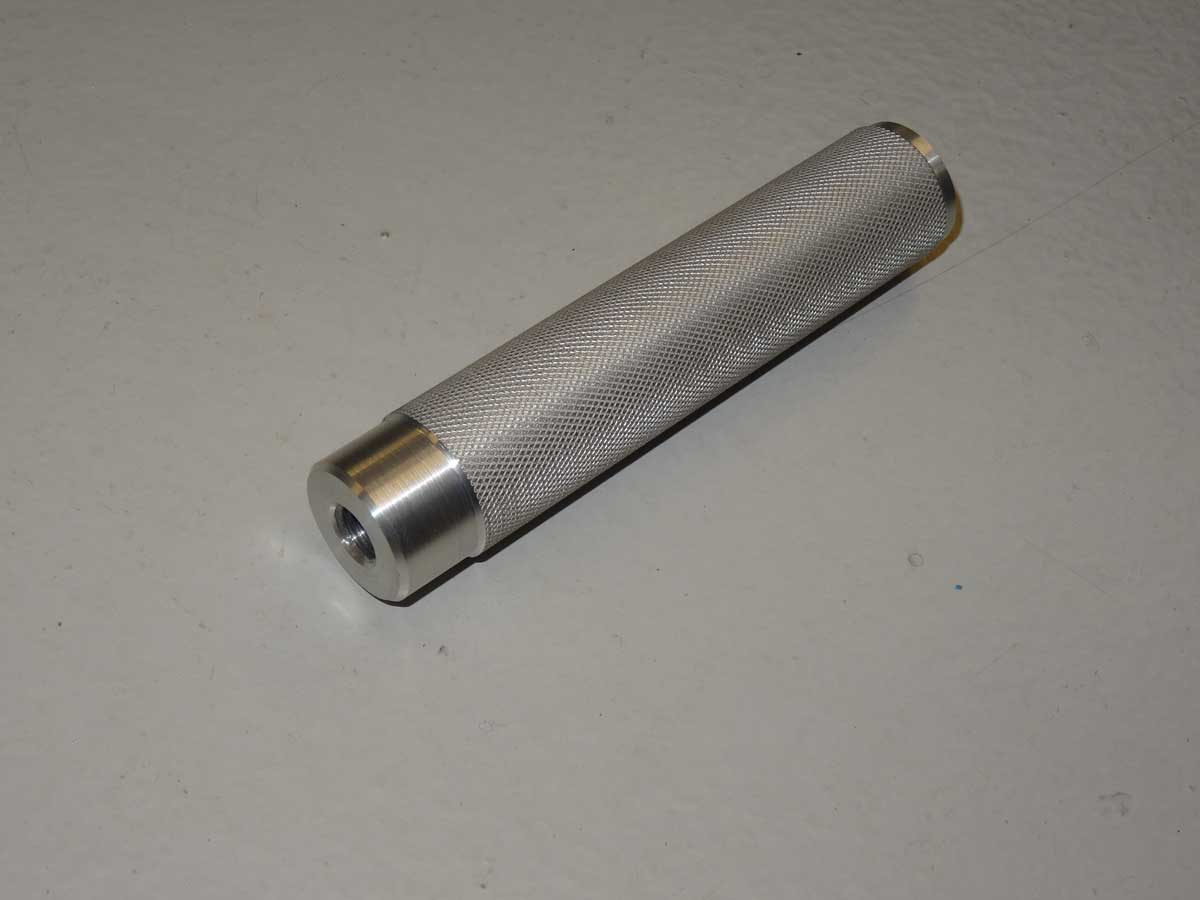
This is the handle with 3 functions: Tensioning the belt, tracking the belt and holding handle to move the belt grinder from vertical to horizontal position and vice versa. Since I have a lathe, I deviated from Jer's plans and turned the handle from aluminum and additionally knurled the surface. I also made the handle slightly thicker (30 mm) and longer (150 mm). The larger diameter makes tracking easier and the longer length also makes it easier to turn between vertical and horizontal (larger lever arm).
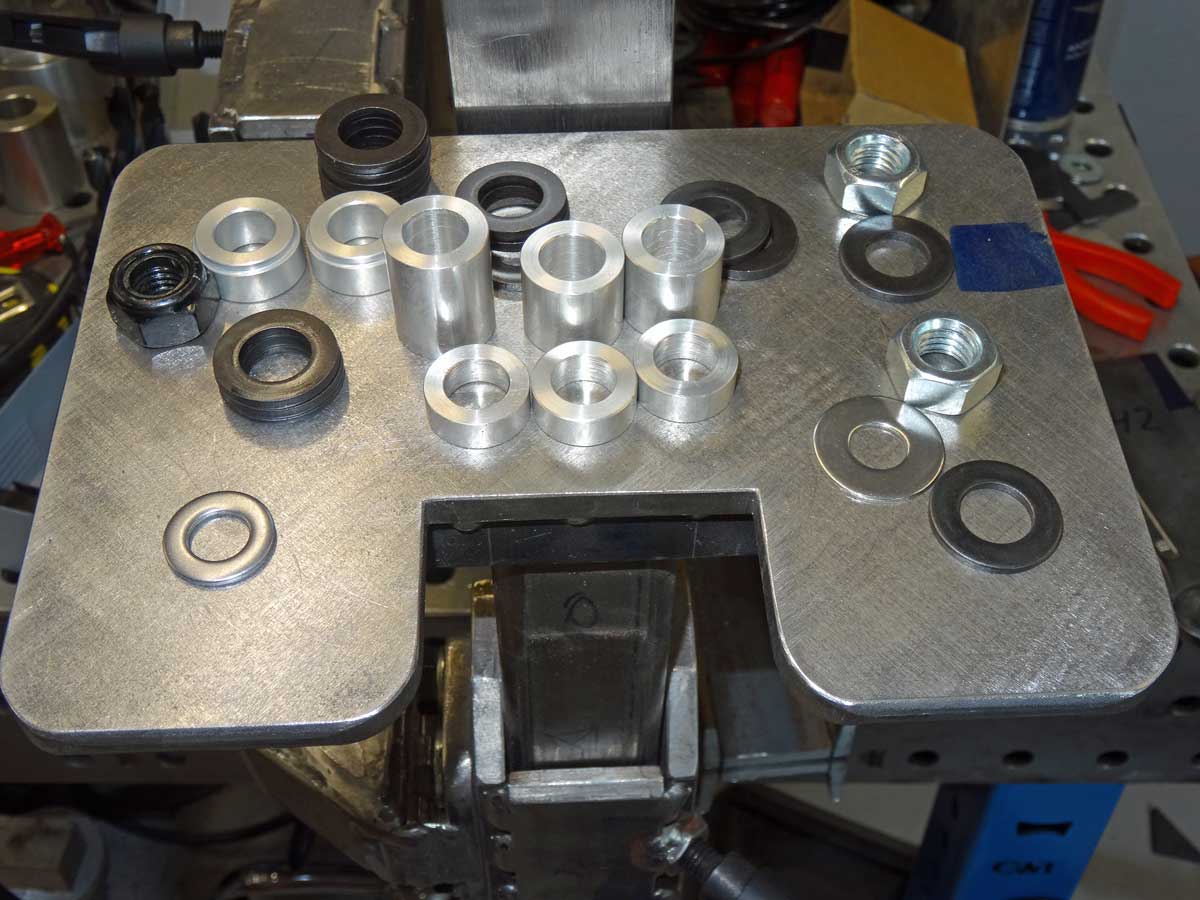
You can easily use washers as spacers and play around with the number of them for the thickness. I did the same, but when I had the right thickness, I turned a suitable spacer ring from aluminum. This is purely cosmetic and has nothing to do with functionality :-)
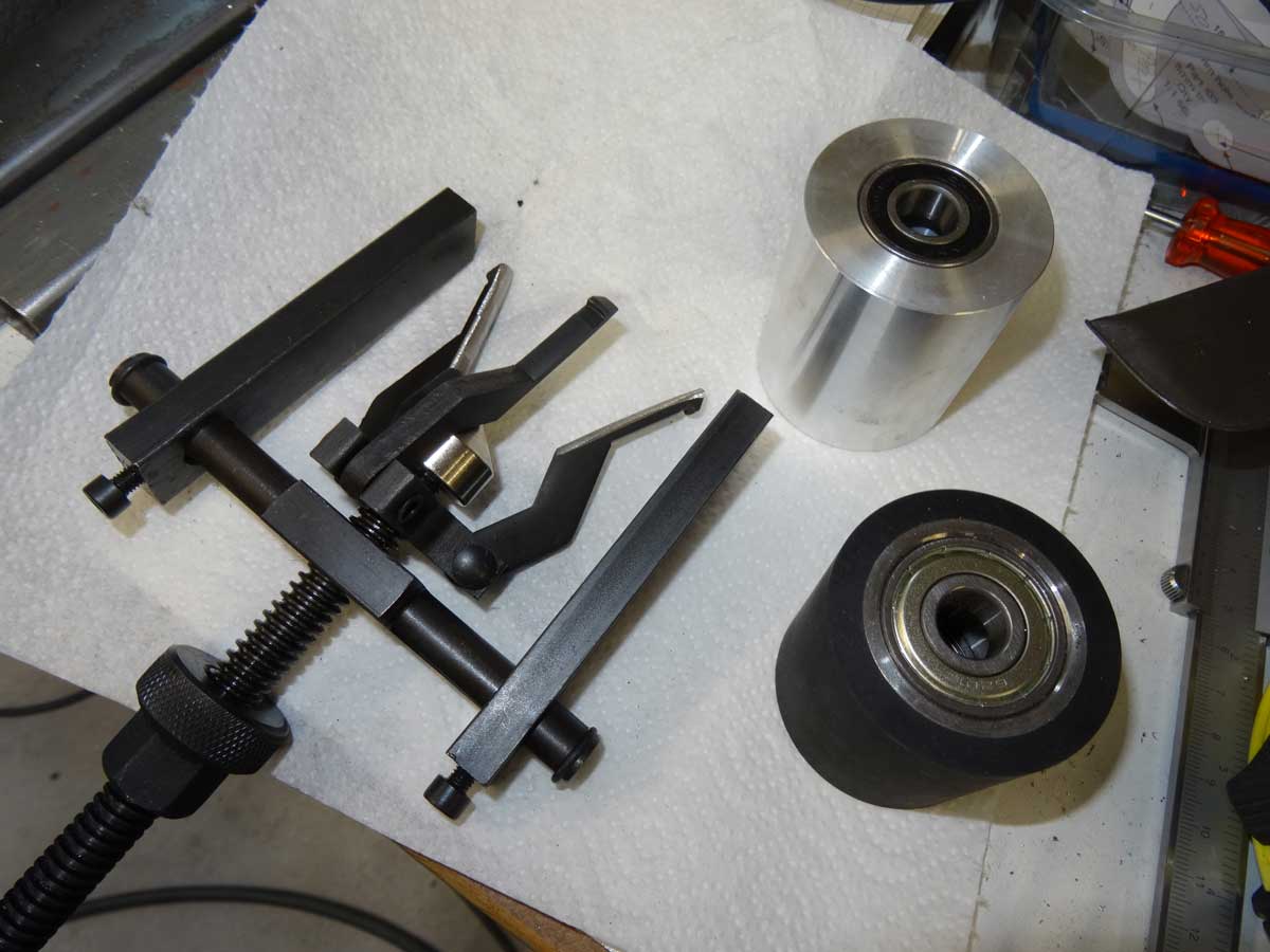
Not all of my aluminum wheels had metric bearings with an inner diameter of 12 mm and above all I had 2 wheels without spacers! This of course makes it impossible to apply force to the 2 inner rings of the ball bearings with a screw without destroying the bearings … This means that the first thing I have to do is remove the bearings with a puller. I had the puller, but the 3 arms were too thick to guide them into the ball bearing ring. This was the time to test my belt grinder productively before painting. I only had to remove some material from the inside of the gripper arms and they fitted into the hole.
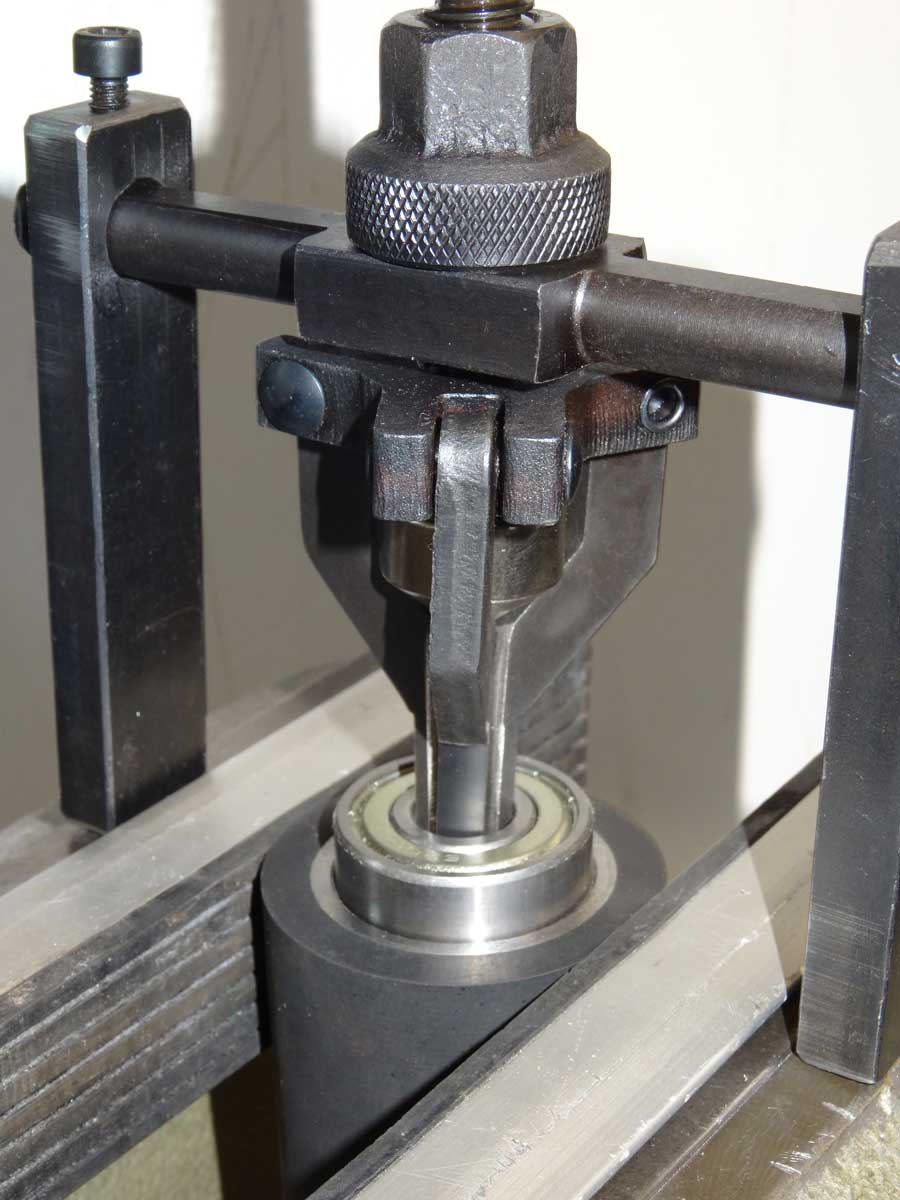
The subsequent removal was then child's play.
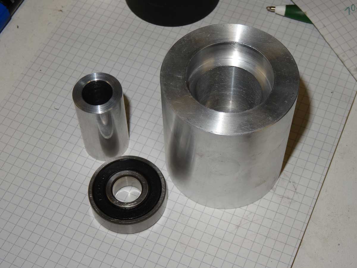
To convert from Imperial to metric bearings, I precisely aligned the aluminum wheel with the dial gauge on the lathe and then turned it to the metric dimension of my new ball bearings. Fortunately, the metric ball bearing is slightly larger, so I had enough material to cut without any problems. Before inserting the 2nd bearing, I put the spacer ring into the wheel and sealed it with the 2nd ball bearing. Now the axial forces acting on the inner rings of the ball bearings are absorbed by the spacer ring.
Next follows
Chapter 3
where I show the steel cutting and welding.
Copyright © 2001-2024 Markus Maurer - all rights reserved
 Creation Date: 17.11.2024
![]()
![]()
![]()