
| Ford Model A |
![]()
![]()

Conversion of wood bandsaw to steel operation (reduction of cutting speed)
Here I show you how I converted my wood band saw to cut steel.
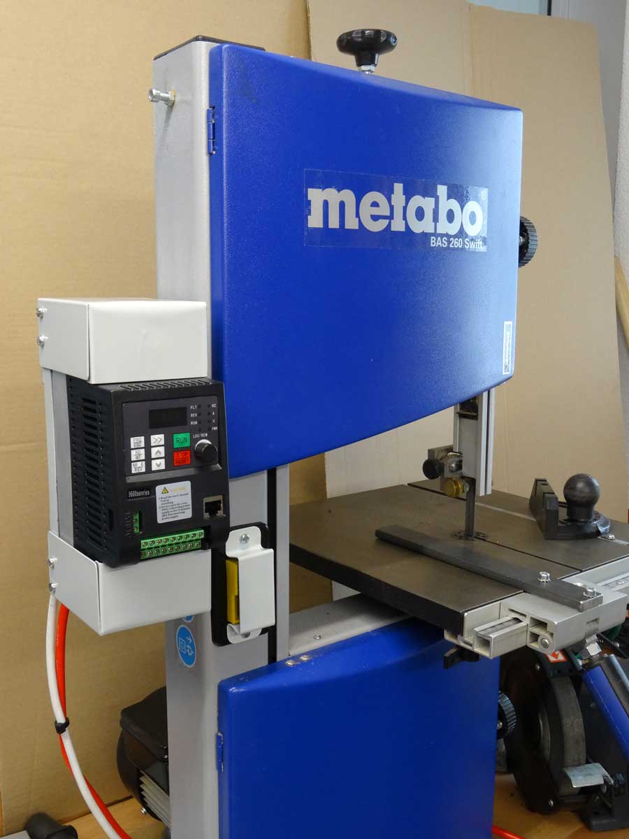
This is an older Metabo band saw. It is intended for cutting wood and I will show you what I have converted so that I can now cut steel. In the picture you can already see the device in its modified state.
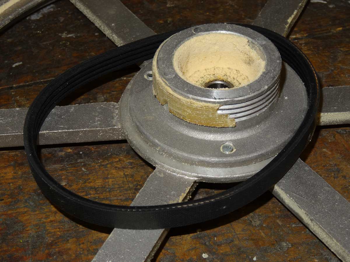
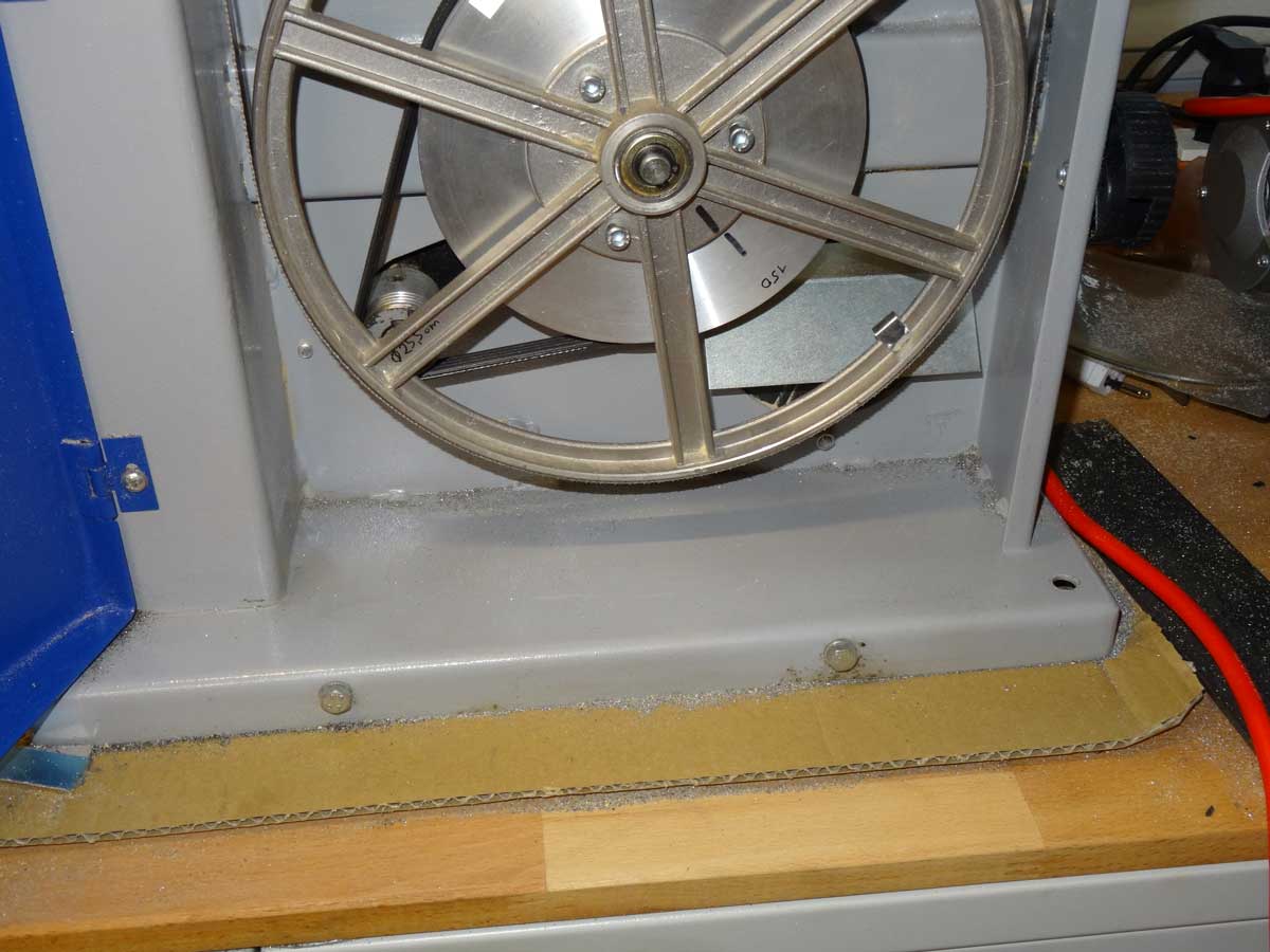
I only to consider 2 points for the conversion. Firstly, I need a suitable metal band saw blade and I have to reduce the blade speed by a factor of about 10. But first I have to put the machine back into operation. Here you can see what was still stuck to the pulley after 10 years of the old belt - the belt has completely disintegrated … The black one is my new V-belt.
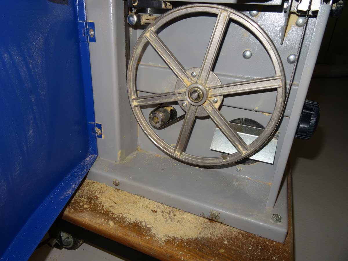
The drive has been repaired and the machine is running again, but still at high belt speed for sawing wood.
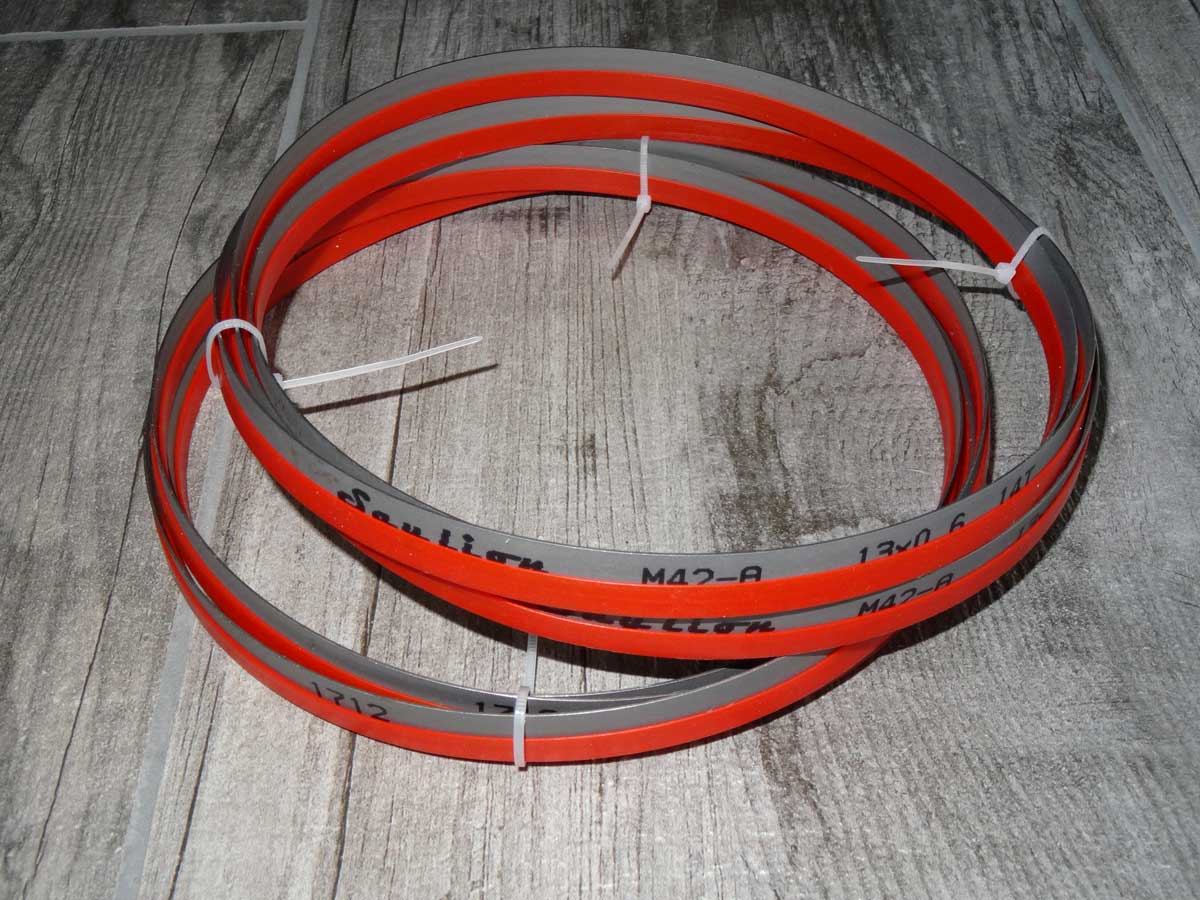
To saw steel, I first need a suitable band saw blade like this one. I did a test after replacing the band saw blade and wanted to find out how critical it is when I run the band at about 13 m/s cutting speed when sawing steel. The first 2 cm when cutting 10 mm steel went very well and I already thought that I could cut steel that way without any problems … Unfortunately, I paused for about 20 seconds during the cut and that was enough to anneal the flanks of the set teeth and the saw blade was blunt :-( It was worth a try, but now I definitely have to reduce the cutting speed from the current 13 m/s to around 1.5 m/s. Only using a VFD (Variable Frequency Drive) I would have to reduce the motor frequency from 50 to 5 Hz and then the motor just stutters and there is no torque left to cut thick steel.
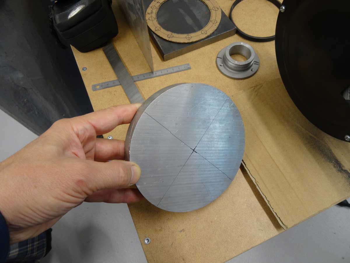
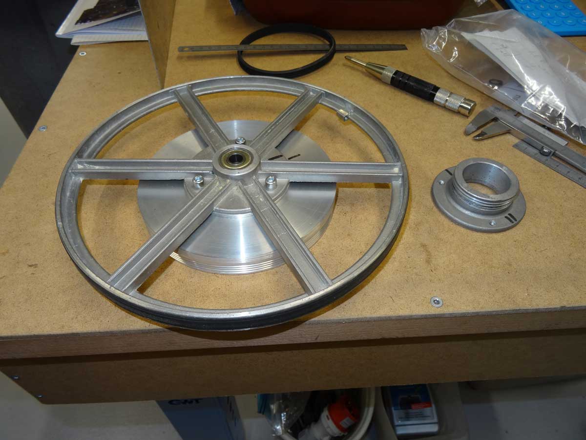
For this reason, I want to make the first step by a factor of 3 purely mechanical. To do this, I use this aluminium disc, from which I want to turn a new, larger drive wheel. At the top right of the picture you can see the original wheel with a diameter of 50 mm and my new one has a diameter of 150 mm.
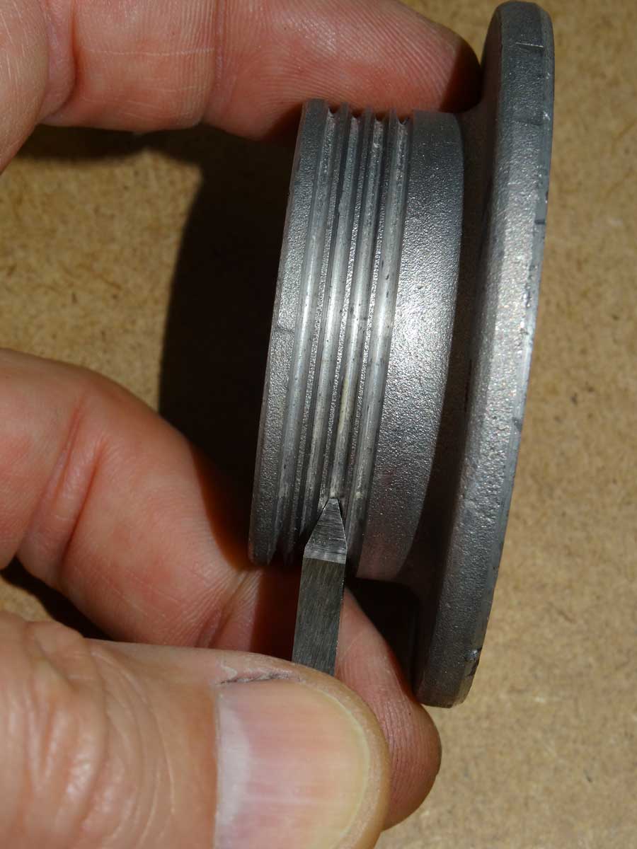
To turn the grooves for the V-belt, I first have to sharpen a turning tool with an angle of 40 degrees.
The 4 grooves have a distance of 2.34 mm between them.
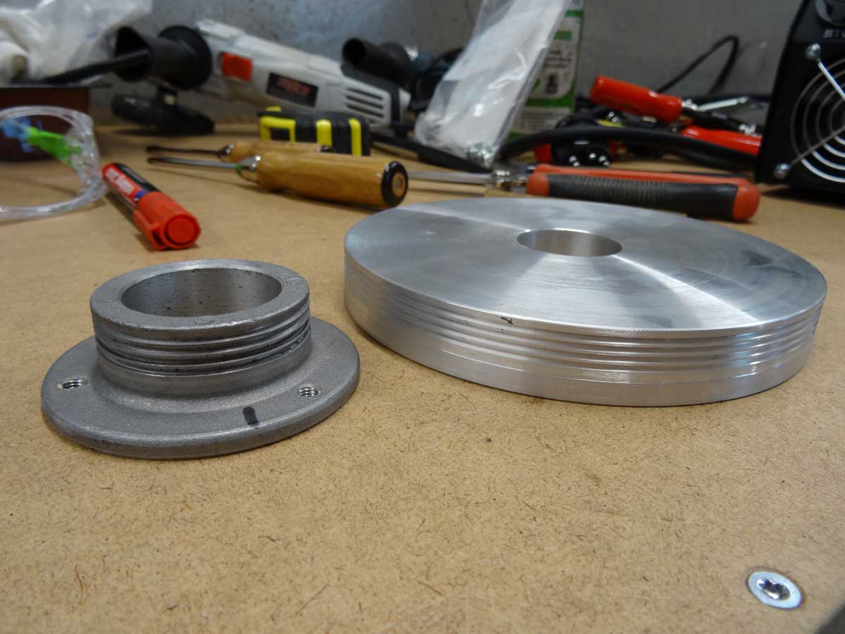
As my disc is slightly too narrow, I have to turn an additional spacer disc.
The 3 holes are drilled, the threads are cut and I can screw the whole thing together.
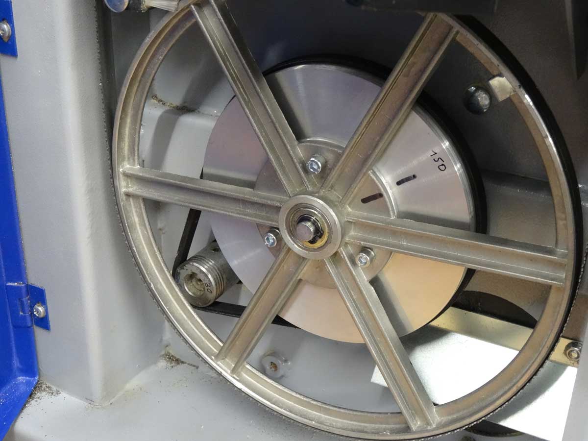
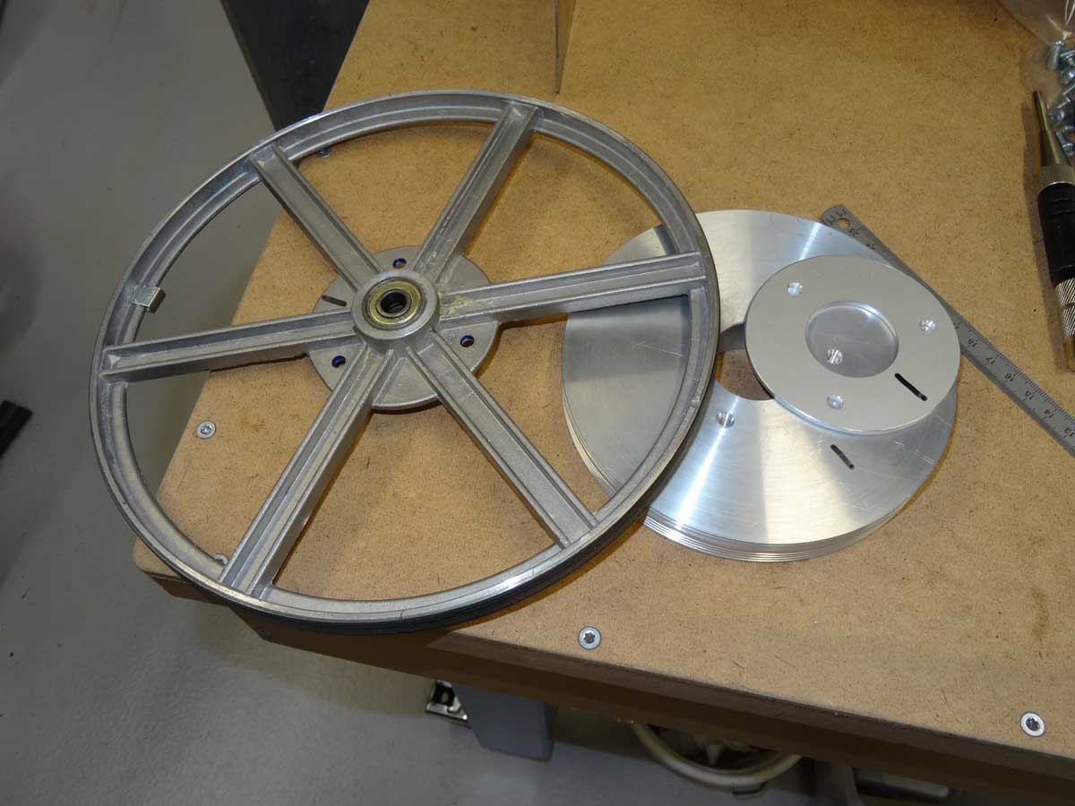
The new V-belt is the right length and doesn't jump out of the grooves.
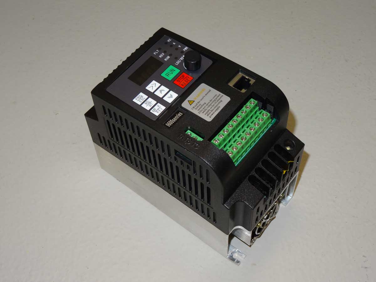
The second stage is to reduce the motor speed, which I do with a VFD (Variable Frequency Drive). This device can be used to operate a three-phase motor at any frequency. This can be lower than 50 Hz, which reduces the speed, but also higher to make it faster, if the motor is designed for this.
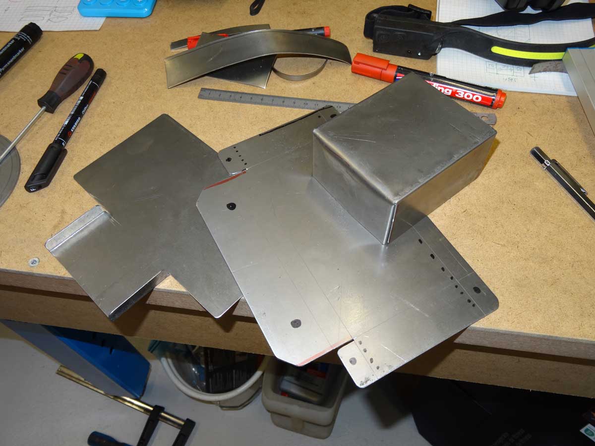
I want to put the VFD in a housing so that the cables and connections are not exposed. I will use 1 mm sheet steel for this.
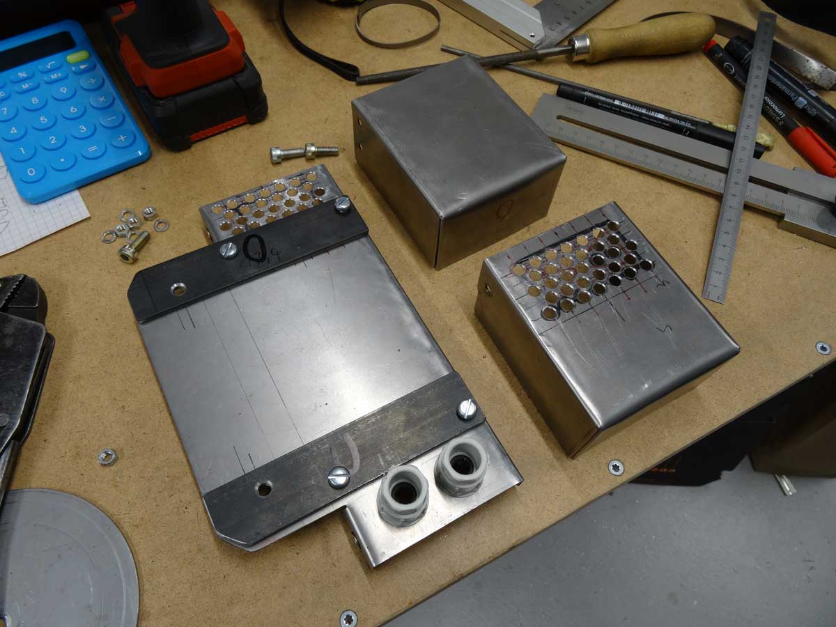
After drilling, filing and bending, the parts are ready for painting.
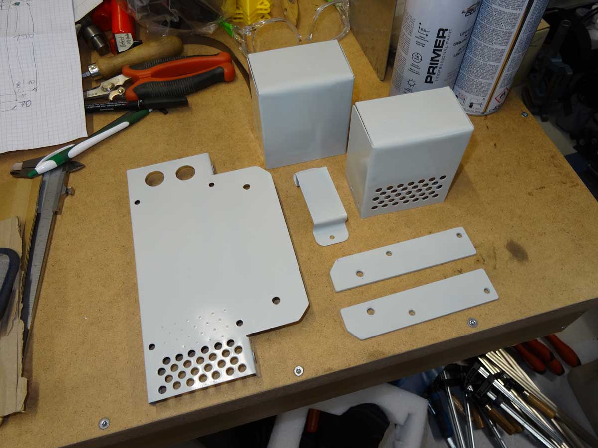
Everything is painted and can be assembled.
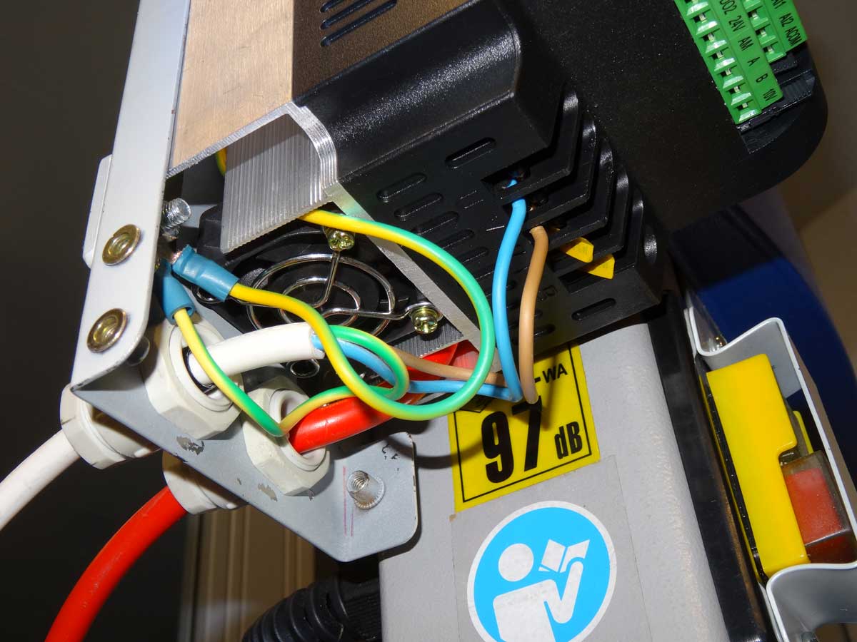
The wiring still has to be done and you have to set all the parameters on the VFD. In my case, it was important to activate 'Torque Boost' to increase the torque at low frequencies.

I 'deactivated' the old on/off switch with a bracket. Also deactivated are the 2 circuit breakers that switch off the motor as soon as the covers of the 2 transport wheels at the top and bottom are opened. The reason for this is that I want to see whether the belt is running smoothly on the wheels when adjusting the belt tension. I can only see this with the cover open and until now I have pressed the switch with one hand when the cover was opened and made the adjustment with the other hand - I think my new variant is less dangerous …
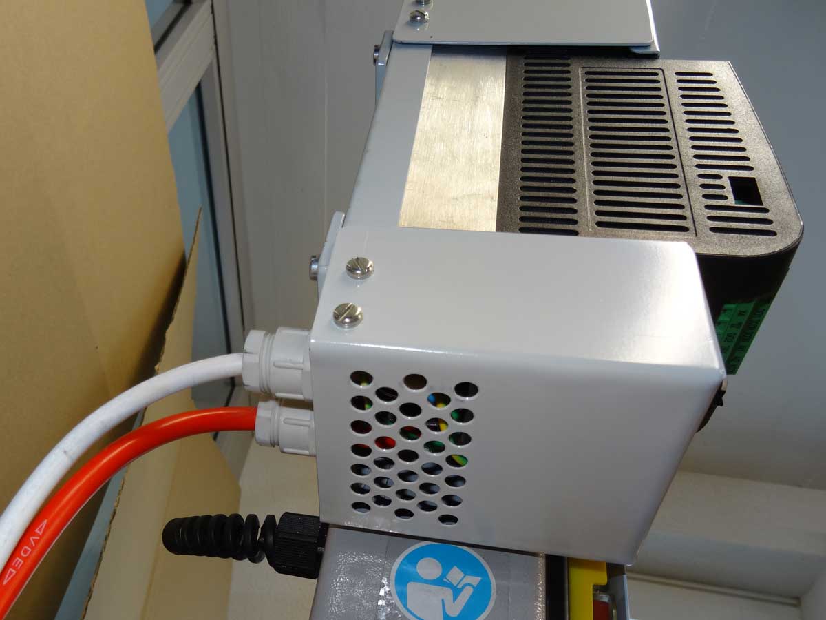
The important thing with the housing is that air flows in from below …
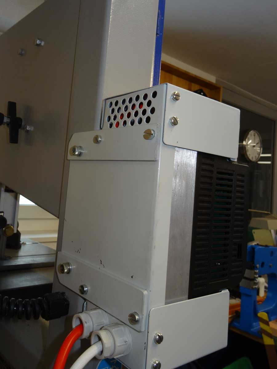
… and can leave the housing at the top at the back. The VFD has a built-in fan that ensures air circulation.
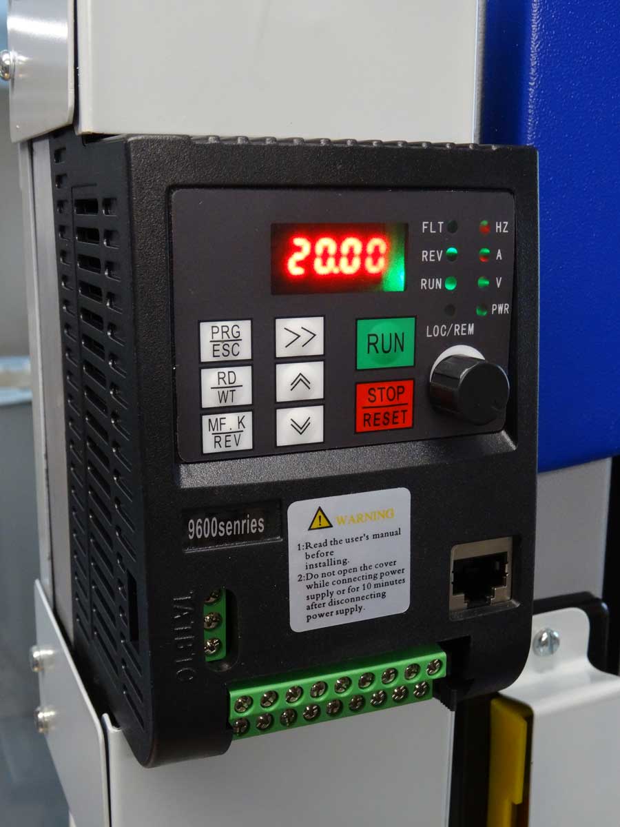
Let's try a first test with 20 Hz, which corresponds to 1.7 m/s cutting speed. I will print out a table and stick it to the machine where I can see the exact relation of Hz to m/s.
The cut on 8 mm steel is clean and the saw blade no longer burns out.
As I always have to remove the fine metal shavings from the housing with a brush, I wanted to make an improvement here.
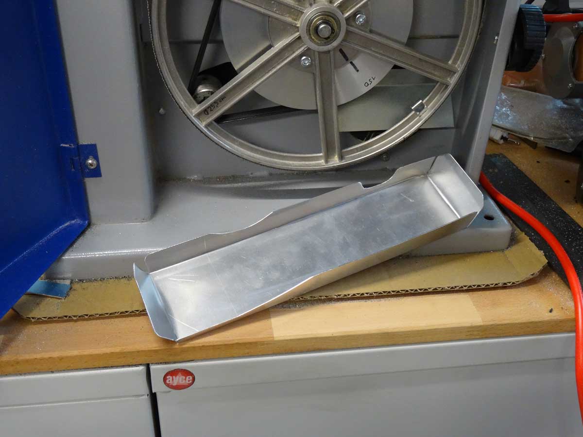
I can simply push this small tray made of 0.8 mm aluminium sheet into the housing and pull it out again to clean it.
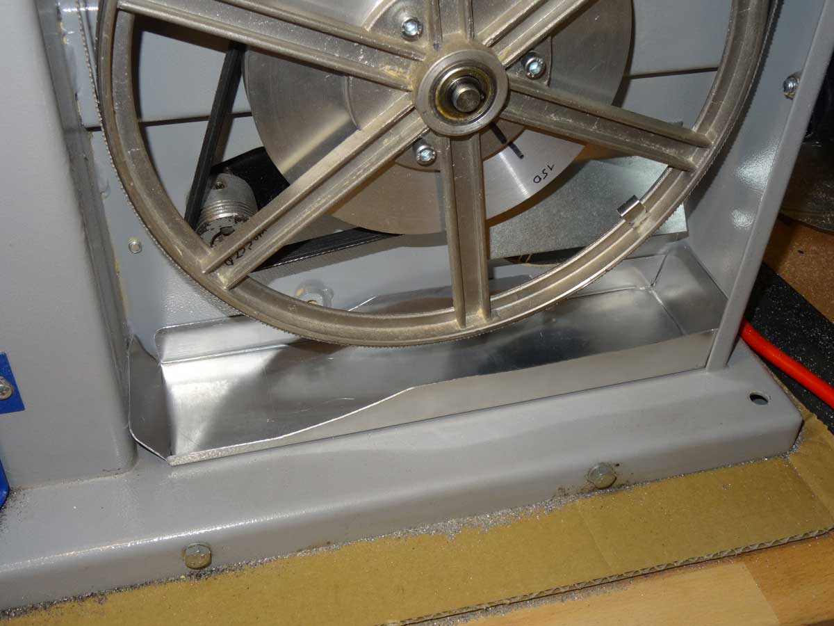
This is the position when installed.
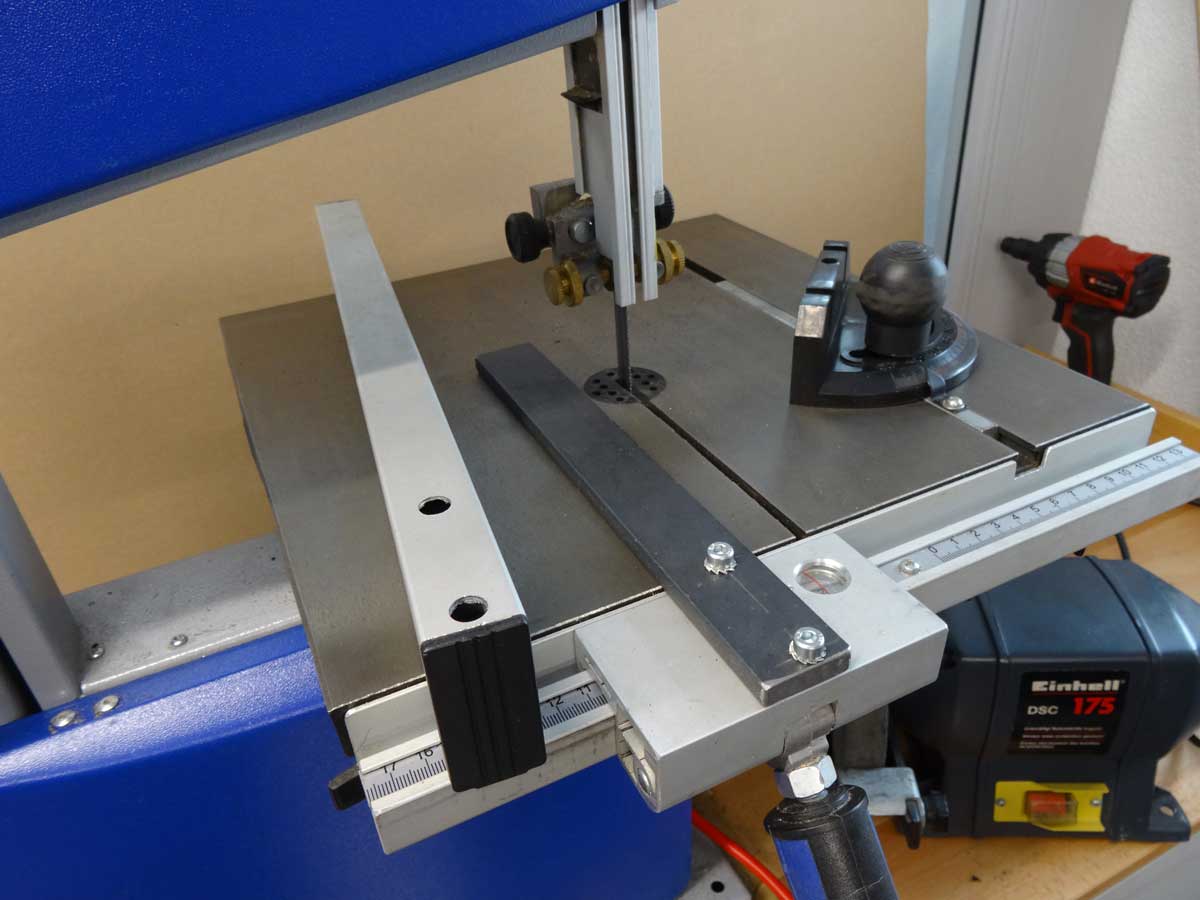
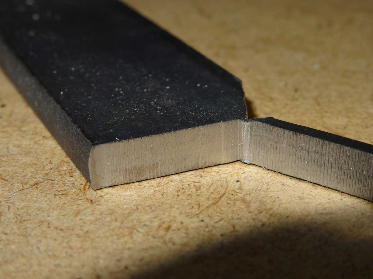
The last optimisation concerns the stop bracket which originally consisted of a large aluminium rectangular profile (left hand side of picture). I have now replaced this with an 8 mm thick flat steel. The reason is that the original stop was too high and got in the way when cutting.
Now I can set all cutting speeds from 1 m/s (12 Hz) to 4.3 m/s (50 Hz) with the VFD. At low frequencies, it could be possible that the motor is not cooled enough due to the low speed, but I have not noticed any negative effects in my tests so far, so I can now start productive operation :-)
Copyright © 2001-2024 Markus Maurer - all rights reserved
 Creation Date: 28.12.2023
![]()
![]()
![]()