| Ford Model A |
![]()
![]()

Ford Model A Pickup Restoration - Building Fuse / Distribution Box - Pulling / Wiring Cables (January 2015)
I'm still working on the wiring and should be finished at the end of February. Beside there are other small jobs to do.
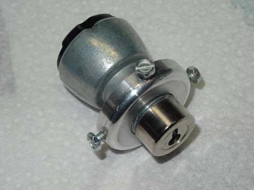
This is my new ignition switch. It is a reproduction part but in a much better quality than my previous one. It is based on the original mounts and therefore cannot be rotated anymore.
The ignition switch is now installed the correct way. The key blade has to face upwards in direction of the 'OFF' and 'ON'.
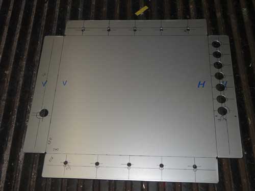
This one will be my fuse and control box and is located under my seat. I made it from 2 mm aluminum sheet and drilled all the holes.
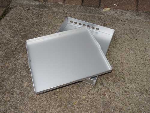
After the base plate and the cover are bent, I had to check whether the cover does fit or not … it does due to the fact that I've made it some mm larger in size than the base case. To remove the cover easily, I've bent it on two opposite sites slightly outwards.
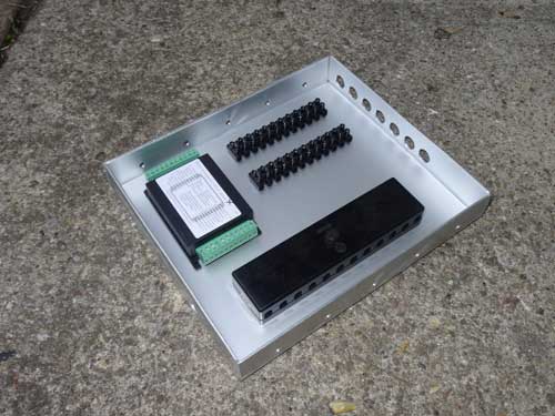
This is the position of my flashing / hazard lights control unit which offers everything I need: 6V positive ground, connection for trafficators and turn signals, also a hazard function where the trafficators remain inactive (to protect their coils).
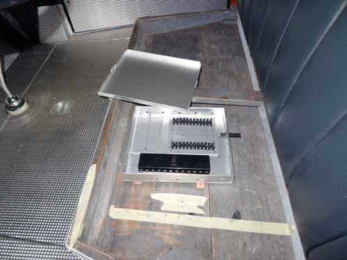
This will be its position under the seat.
In order to have a clean ground contact everywhere, I will use a separate wire to all devices. This distributor is fixed to the crossbar of the frame.
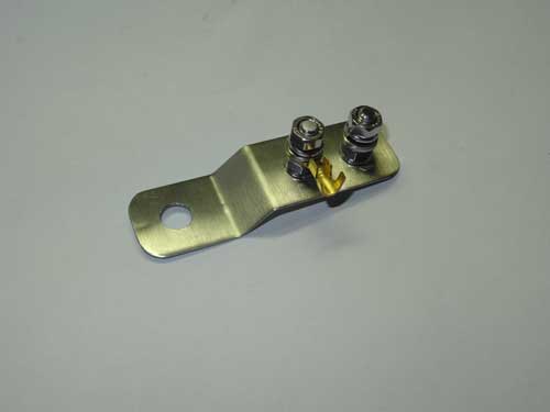
For the head light and turn signal ground are these two connectors. They will be fixed to the frame with a screw of the front shocks and are invisible, hidden in the U-profile of the frame.
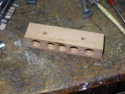
Cables must be properly guided. This wooden part will be mounted under the cabin.
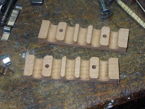
It is made from two halves of beech wood.
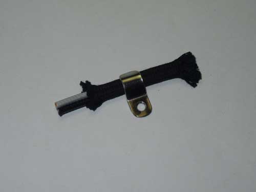
To fix the windshield wiper cable I was looking for suitable brackets but could not found versions which would (optically) fit.
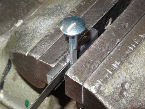
Therefore I made them out of 1 mm stainless steel sheet metal. The tool I've used is quite simple. All you need is a piece of flat steel and a bolt. I have cut out a small piece of the steel part and slightly reduced the thickness of the carriage bolt I used. Then put all parts in a vice and …
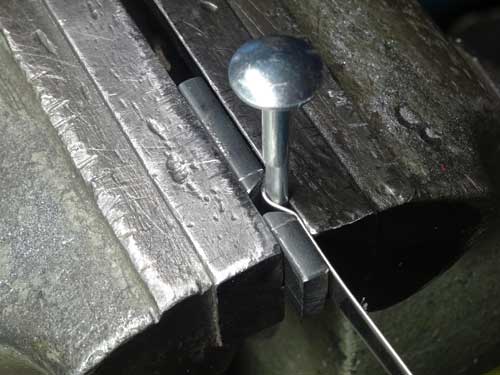
… squeeze - the first clip is made!
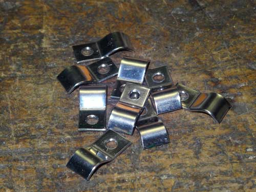
They already have the correct length but the corners are not finished yet.
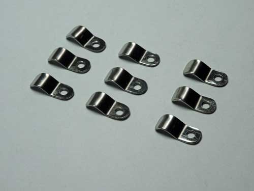
And this is the final result.

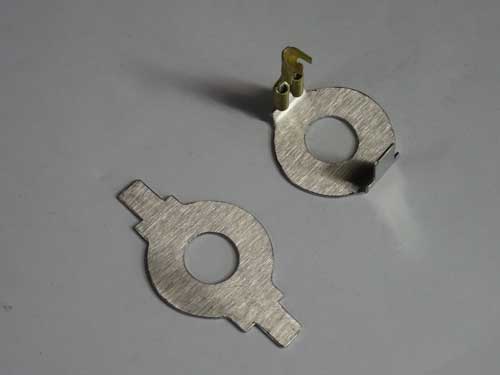
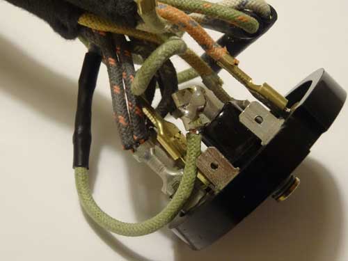
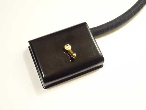
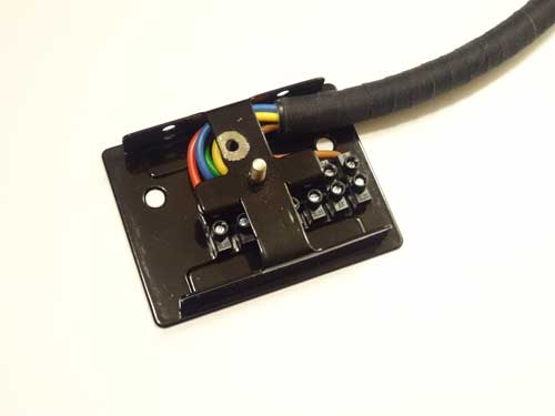
This is the light switch which is mounted below the steering column. Unfortunately the producers of this reproduction part did not thinking very much regarding the blue/yellow wire located in the middle. This wire is soldered to a bolt which must have some end play to move up and down. But when the case is mounted, there is no free space to move in any direction!
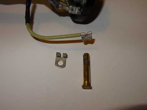
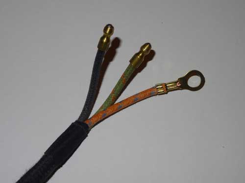
I had to think about a better solution and used this shortened cable lug.
I soldered it together in the slot of the brass bolt in an angle slightly downwards. I have also enhanced the length of the cable by 2-3 inches. Now it can move without any problems.
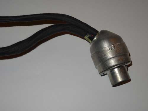
This is the switch with mounted case.
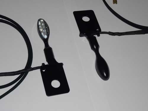
My LED indicators are also ready for installation.
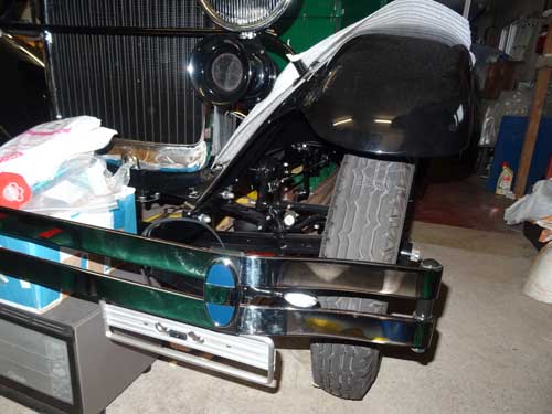
Hard to see are they mounted in in the middle of the bumper.
The head lamps are mounted now without the connector and with a separate ground cable.
Each bulb has now a good ground connection made with a cable.
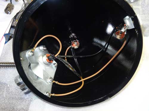
This is my homemade distribution box for the rear lights.
And this is a view inside the box.
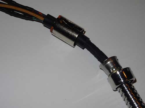
My self made cable harness is nearly finished.
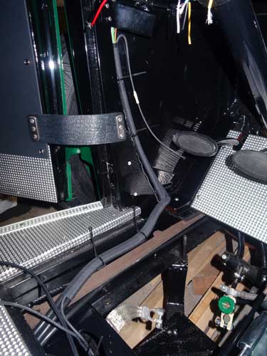
This is the temporarily mounted harness at the A-pillar on the driver's side.
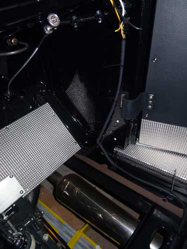
And here is the one on the right hand side. By the end of next month, the cabling will be finished. I hope not to make any short circuits in the meantime, but this should be no problem because I have installed a main fuse and 10 smaller fuses for several devices and bulbs - hope I've installed everything correctly :-)
Copyright © 2001-2024 Markus Maurer - all rights reserved
 Creation Date: 17.02.2015
![]()
![]()
![]()