
/ford_a/2024_05_fluester_kompressor_mit_zusaetzlicher_kuehlung.en.html
![]()
![]()
I bought an Einhell TE-AC 50 Silent compressor some time ago. I wanted a silent compressor that makes very little noise and can be operated without causing hearing damage. I can also use it to operate my compressed air rod sander. The problem is that the compressor heats up quickly and cools down very slowly from a high temperature. The reason for this is that the motor is only cooled when it is running. I wanted to tackle this problem and give the compressor an active cooling system so that I no longer have to wait so long for it to cool down.
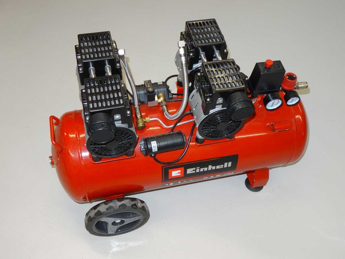
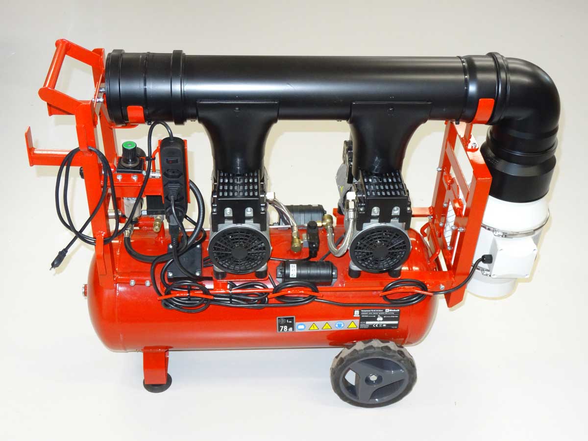
This is what my 'TE-AC 50 Silent' compressor looks like and I now want to modify it a little bit.
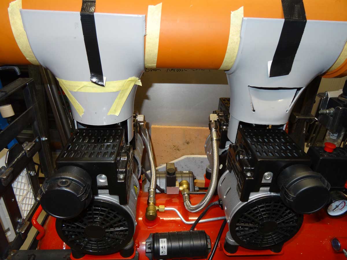
The pipes for the additional cooling come from the DIY store and are both pipes from the sanitary area and connections for gutters (gutter drain).
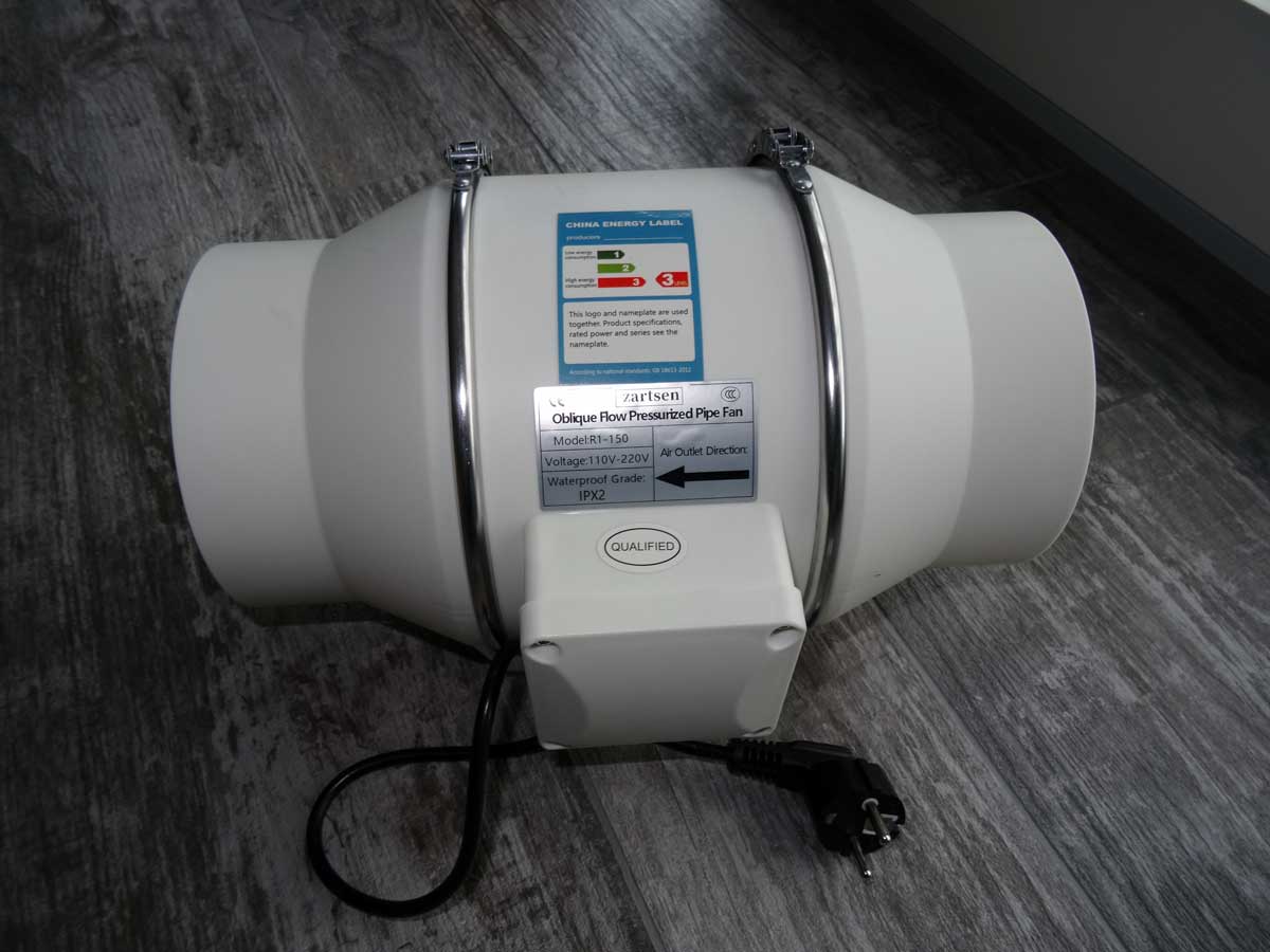
The air required for cooling comes from this fan with a pipe diameter of 150 mm and a flow rate of 540 m3/h minute. It is also very quiet - after all, I don't want a silent compressor and then install a ventilation system that ruins all the peace and quiet.

First, I build the bracket on which I will screw the fan. The fan should be easy to remove, as I may want to use it later for my large compressor.
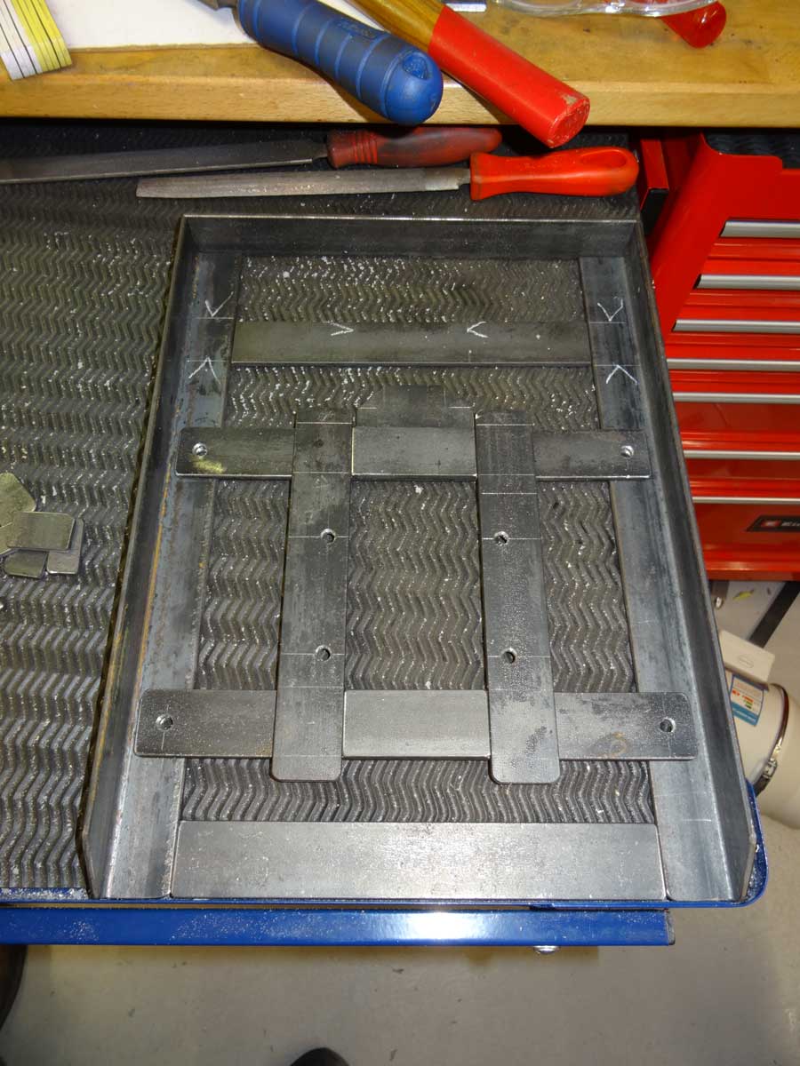
All the parts are cut to size and I can start welding.
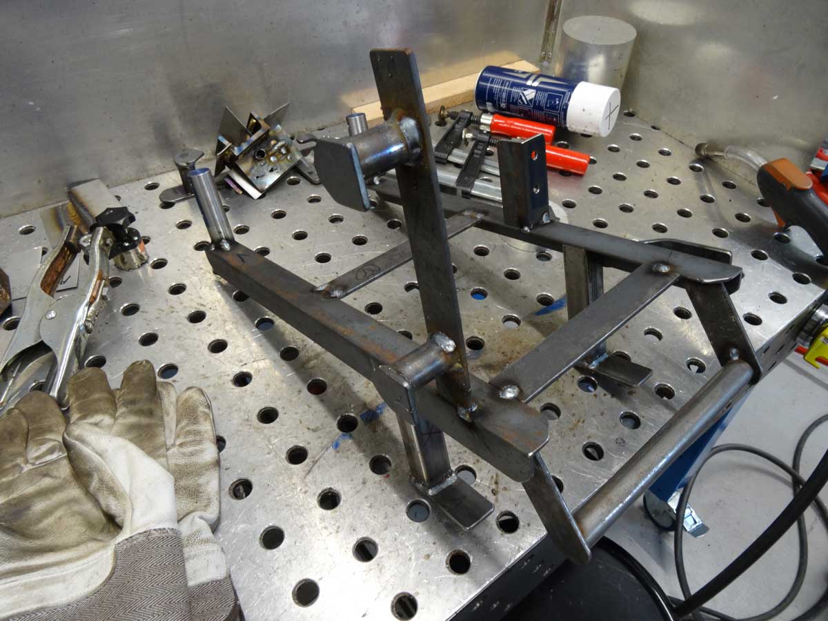
I will also take this opportunity to attach additional holders for compressed air hoses etc.
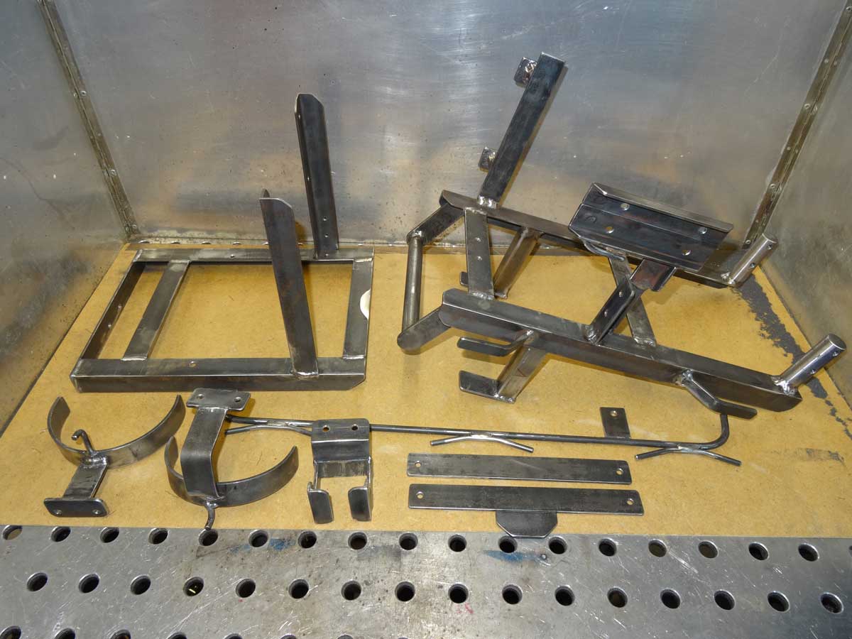
All the parts I need are welded and just need to be painted.
In a first attempt, I opened the vertical tubes on the side to get some air to the motors on the left and right of the stator. However, this was not a good idea and I immediately discarded it. The reason is that in this case too little air reached the stator.

Now the assembly of the air cooling parts takes place to see if everything fits.
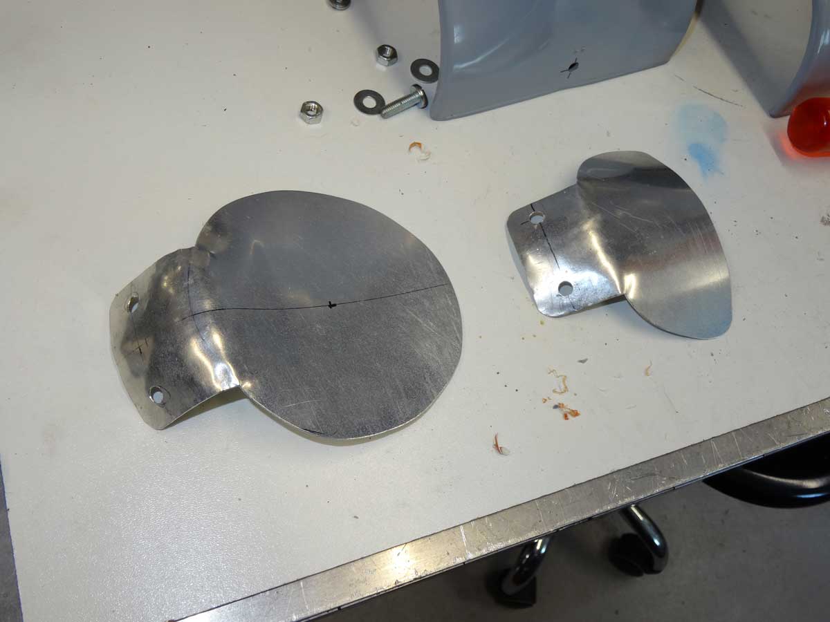
What I still have to do is to adjust the 2 openings so that both let through the same amount of air and the 2 motors are cooled equally. For this I use aluminum flaps made from 0.8 mm sheet metal.

The 2 flaps are mounted in the pipe and can easily be bent slightly for perfect adjustment.
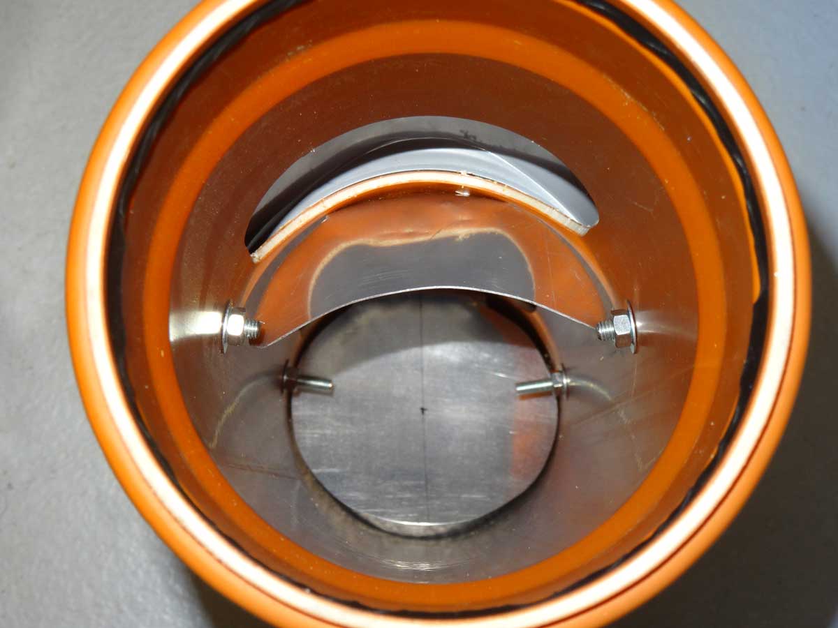
The first flap directs part of the air flow into the first outlet, the second then directs the entire remaining air flow through the second opening.

As it is somewhat difficult to adjust the air flow precisely by feeling it by hand, I did the whole thing with an anemometer, which shows me the speed of the air flow at the 2 outlets.

To ensure that no air escapes before it reaches its destination, the top edge is sealed with foam tape.

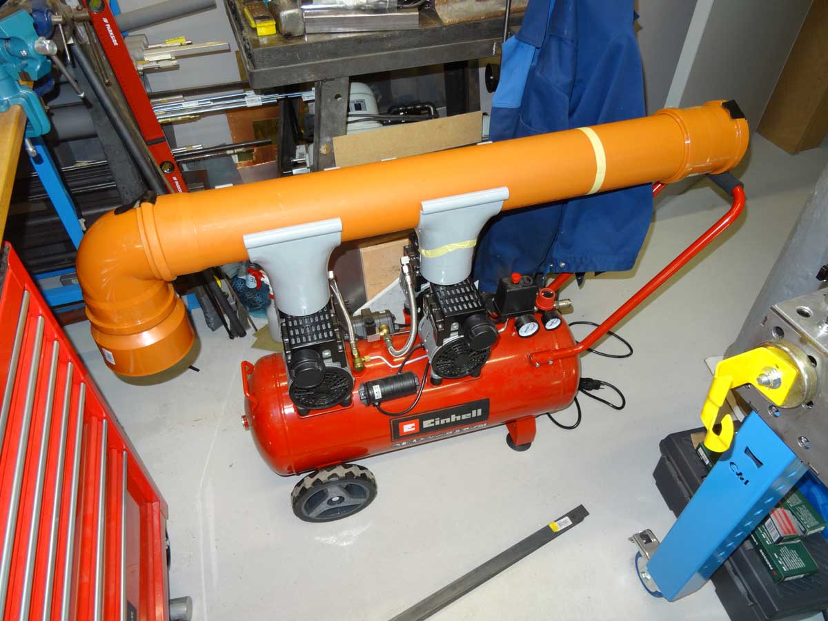
Once assembled, the pipe system for cooling looks like this.
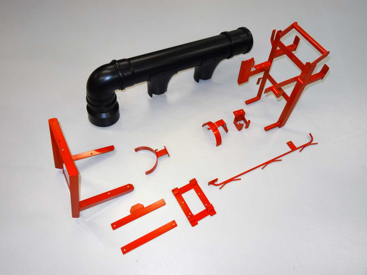
I chose the same red color as the compressor and painted the pipe system in matt black.
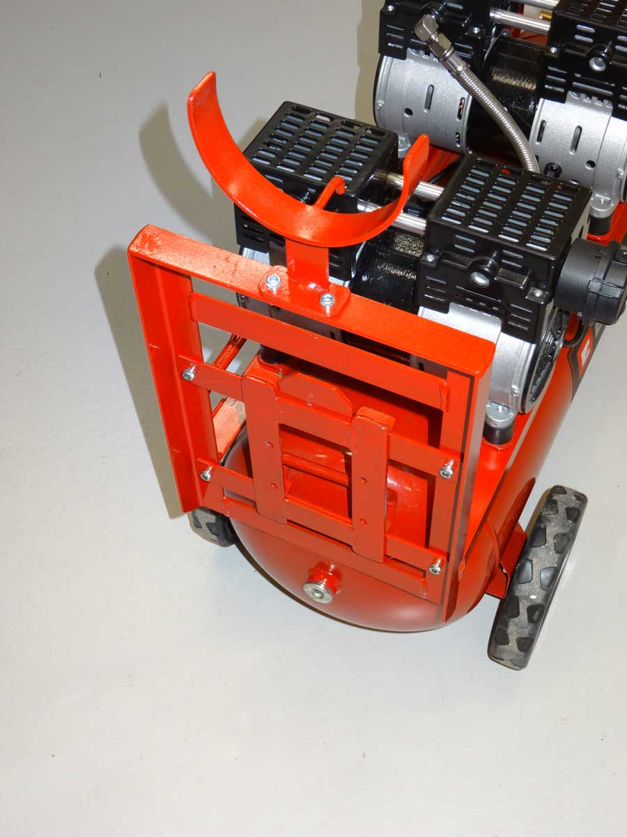
This is the side where the fan is mounted.
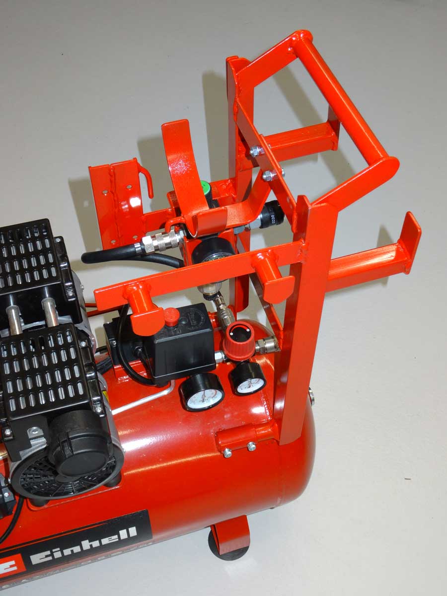
On the other side there are various holders for hoses and also an attachment for a pressure reduction valve with water separator.

This is the holder that is screwed to the fan and is only hooked in on the compressor side.

My active auxiliary cooling system for my compressor is finished.
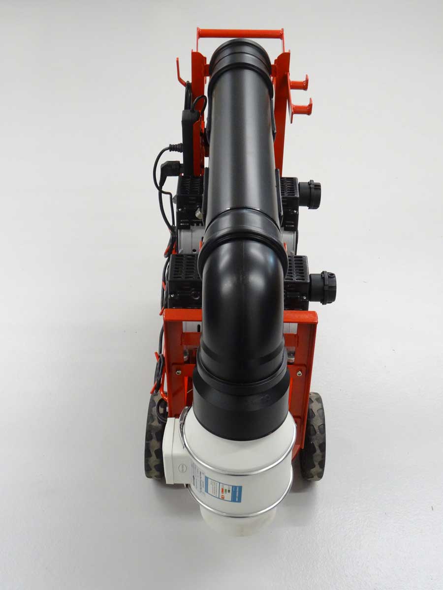
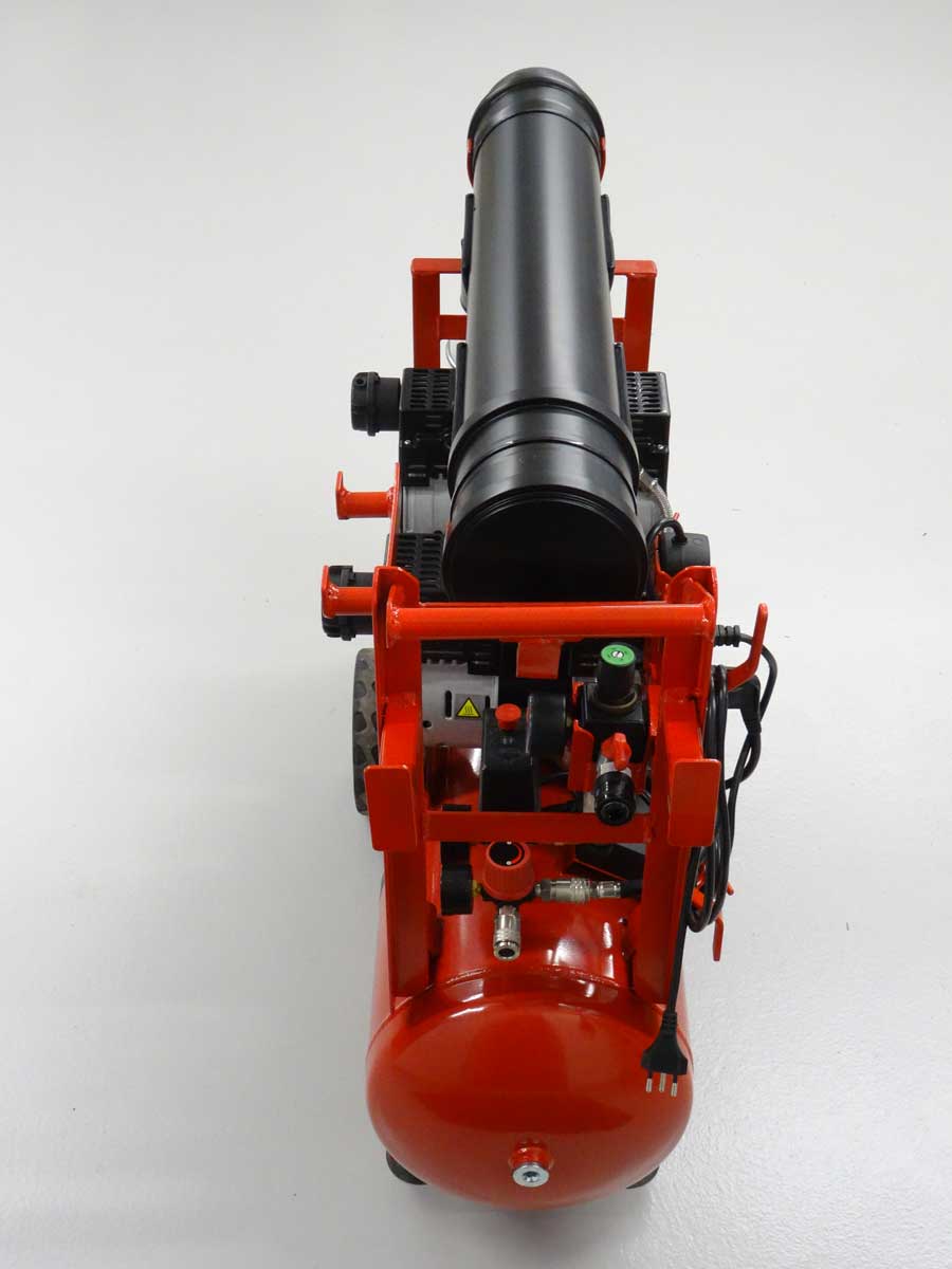
This is the compressor view from the opposite side.

Here are a few more photos from other angles.

Here the compressor is fully loaded with hoses.
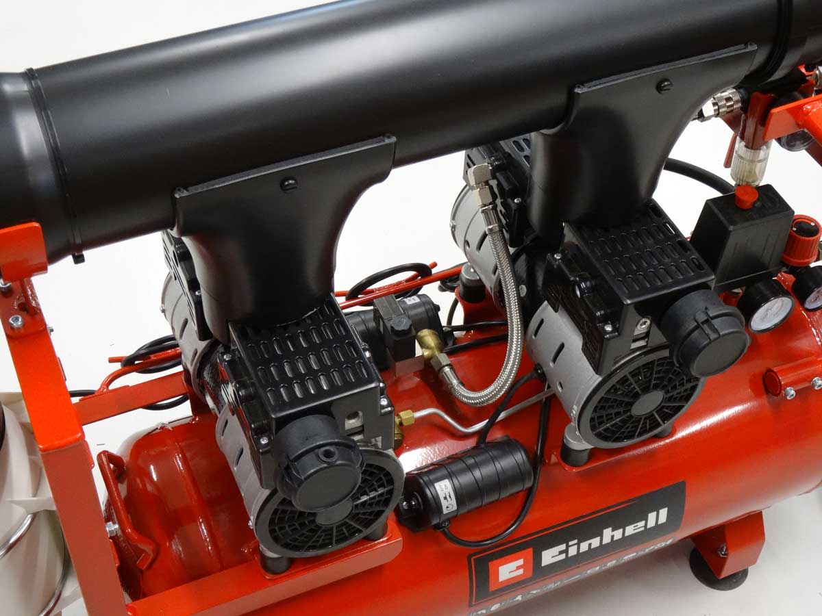

The greatest heat is generated at the stator (black part in the middle) and this is now optimally cooled. Some of the air is also blown sideways through the cylinder head cover (slotted plate) and thus also cools the 2 compressor heads to the left and right of the stator.

I chose the somewhat complex cable routing so that I can simply unwind the cable and then pull the fan out of the bracket. This means I can use the fan for other purposes if necessary and remove it without tools.

Now, of course, I need an official measurement to show what my compressor cooling system is now achieving and whether it was worth going to all the trouble and expense. For my series of measurements, I measured the surface temperature at the stator (which is the hottest). For comparison, I measured both stators and they showed identical values, i.e. the adjustment of the 'air flaps' is correct.
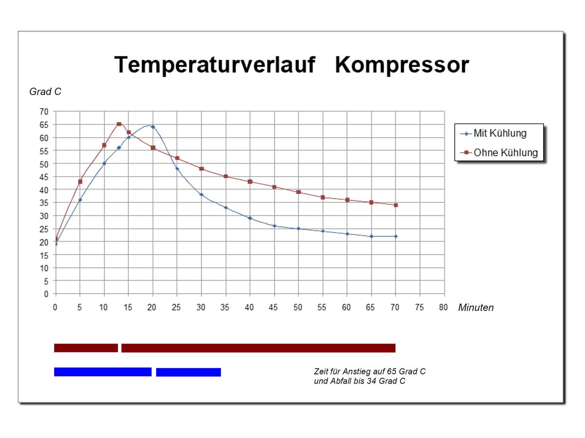
Here are my test results and I have chosen the following scenario. I let the compressor run until it reached the maximum pressure and stopped the engines automatically. I then immediately released the compressed air until the engine restarted and repeated the whole process until the the temperature of 65 degrees C is reached.
The measurement curves now show the following: The red line is without active cooling (original state). The blue line shows the temperature curve with active cooling over the entire time. As you can see, with cooling, it takes 50% longer until the temperature of 65 degrees C is reached. The subsequent cooling down to 34 degrees C takes 57 minutes without cooling!!! With cooling it takes only 14 minutes.
Conclusion: I know that compressors are not designed for continuous operation, but I now know that my actively cooled version of a compressor is within a healthy temperature range. The motor and compressor are protected and the built-in thermal protection no longer has to kick in.
Copyright © 2001-2024 Markus Maurer |
Creation Date: 06.06.2024 |
Last Modified: 05.12.2024
![]()
![]()
![]()